TE Toolbox for
Siemens NX
Realizing Model-Based Definition with Technical Elements in Siemens NX.
neoapps | Products
With the TE Toolbox you standardize your design in Siemens NX with the help of technical elements. With it, you can easily master the transition to model-based design (MBD). The result is a continuous process chain and a high degree of automation in product development.
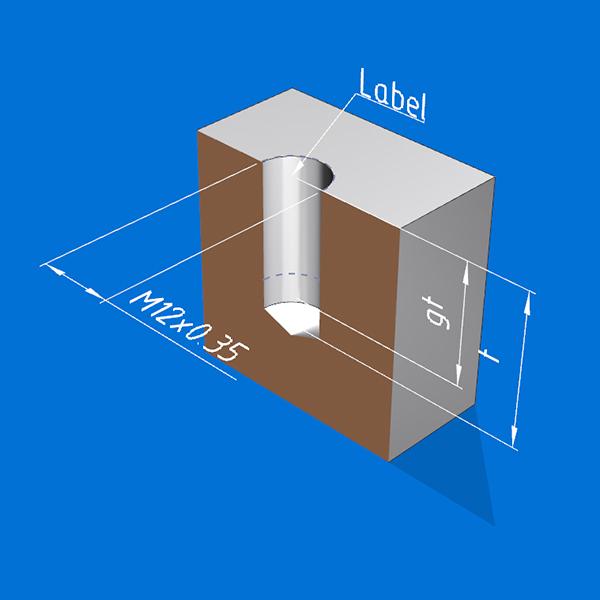
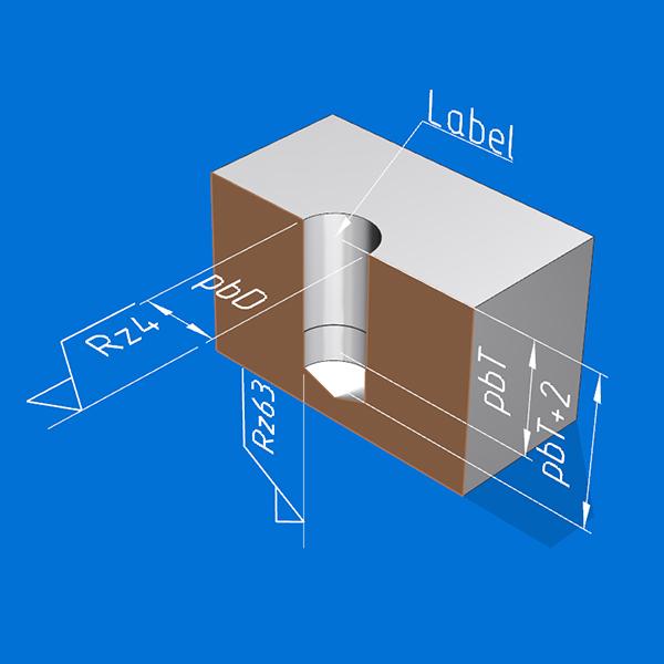
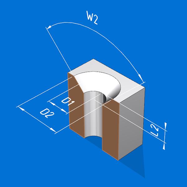
What are Technical Elements ?
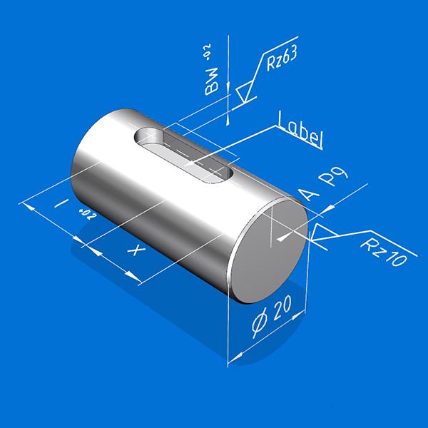
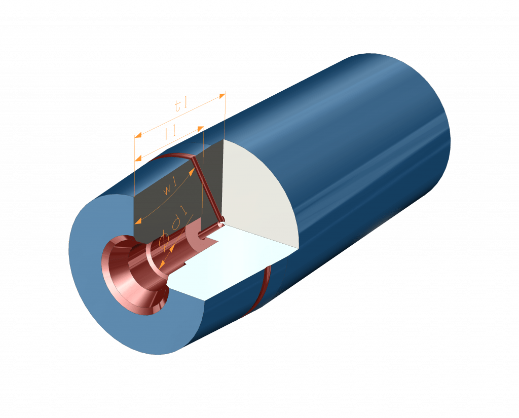
Technical elements (in short: TE) are standardized and recurring design features such as holes, undercuts, bearing seats, pockets, gear teeth, etc. You can use them to build your 3D model directly in NX. The technical elements carry all the information (PMI, attributes, colors, etc.) that you need to automate your downstream processes. The design intention is thus reliably recorded and linked to the model associatively. They therefore do not have to be specified again later in time-consuming and error-prone rework.
Example:
Automated Process Chain with TEs
The result is a consistent, persistent and highly automated overall process in product development. All the necessary information is available directly in the 3D model for each process step. This design approach allows you to achieve a very high degree of automation in product development. This saves high costs and the time for product development is greatly reduced across departments.
The Benefits of TEs in a nutshell
Cost Savings
High costs are saved along the entire process chain by standardizing the design and avoiding media breaks.
Automation
All metadata for subsequent process steps is available in machine-readable design features.
Time-to-Market
Time to introduce innovative and new products reduced to a minimum.
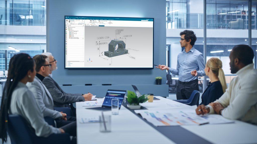
Realizing MBD in Siemens NX
With the TE Toolbox you can switch to Model-Based Definition in your product development, as all production-relevant information is already contained directly in the 3D model. In contrast to a classic UDF (User-Defined Features) or a reusable object, not only geometry information is introduced into the 3D model. Rather, a wide range of metadata also enters the construction. A separate 2D drawing derivation thus becomes obsolete. You can easily switch to a drawingless production. This saves you valuable time in product development and at the same time increases the consistency of your production and your measurement technology.
Thanks to the Technical Elements, we have all the metadata for our follow-up processes directly in the 3D model. This means that manual rework in CAM or CMM is no longer necessary. The result is a continuous process from design through production to quality assurance.
All metadata directly in the model
Attributes
Edges, planes, sketches, and much more. Ideal for processes like CAM and CMM.
PMI
Parameters of the TEs are automatically generated as PMI. Also for shape and position of the TEs.
Colour
Areas of the technical elements are colored automatically. Ideal for CAM and CMM.
Names
Faces, planes, sketches, PMI, etc. are provided with machine-readable names.
TE Toolbox Framework
Customized Technical Element.
For various Industries.
The TE Toolbox is a framework that enables the definition of company and industry-specific technical elements. No programming knowledge is required for the implementation. The tailor-made technical elements can be put together simply by configuration. The result is a design library for modeling innovative products in Siemens NX for all sectors such as classic mechanical engineering, mold making, aerospace and wood construction.

Looking for a customized Technical Element for your reuse library?
Talk to our experts and learn more about the multitude of possibilities.
Standardization starts in CAD
One Standard. For all designers.
With Technical Elements, diverging approaches in the design is avoided. Instead, 3D models are standardized and structured uniformly from the very beginning. In this way, the models always comply with global design guidelines. Ideal as a basis for the automation of subsequent processes in the context of a streamlined and digital manufacturing chain.
MBD Logical Rules and Technical Elements
Complex MBD Logical Rules for the automated generation of PMI.
With Technical Elements you extend your options when building complex and effectice MBD rules. All metadata such as attributes, names or colors can be used to easily identify the objects in the 3D model.
Better Quality with Technical Elements
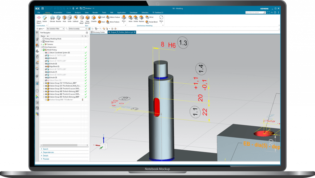
Unique IDs for each inspection feature of a Technical Element.
The TEs perfectly prepare your 3D model in NX for the tasks of QA by numbering all TEs without gaps. Each TE carries a unique ID number. Each associated PMI receives an index to this ID number. This numbering system ensures a complete listing of all inspection features in NX CMM, your CAQ system or simply in a inspection feature list in Excel format.
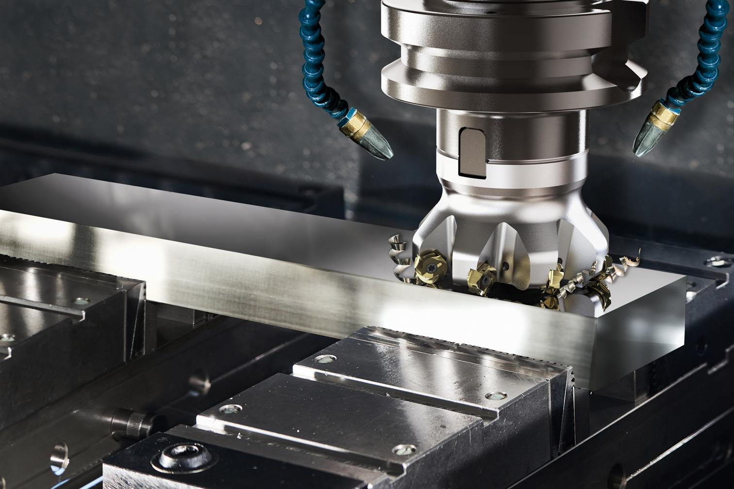
Technical Elements
in Manufacturing
All metadata is available in production for Feature-Based Machining (FBM). Attributes, colors, names and PMI can be retrieved directly from the 3D model. As a result,design features are recognized reliably. This means that predefined milling or turning operations can be easily assigned to the Technical Elements.
Through the use of technical elements in the design, all design guidelines are automatically complied with. This leads to a very strong standardization of the 3D model. Ideal for automating the follow-up processes.
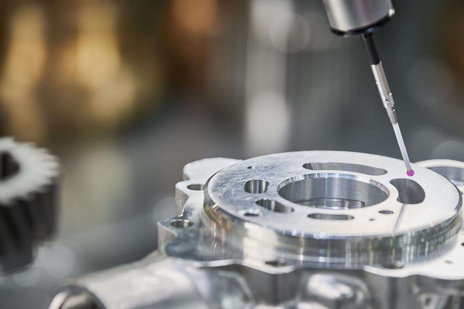
Technical Elements
in Quality Inspection
All PMI in the model are firmly linked to their reference faces. As a result, the PMI is directly available in CMM in a machine-readable fashion. In addition, the inspection navigator of NX CMM can be filled automatically via the Inspection3D module. All general dimension tolerances are also automatically transferred.
“By using the TE Toolbox, we were not only able to achieve standardization in the design, but also to make the entire process much more efficient and faster”
More Highlights of the TE Toolbox
Tolerance Centre
With the TE Toolbox, all tolerances are in the model right from the start. At the push of a button, you can switch the entire construction to a tolerance center model using synchronous methods.
General Tolerance
General tolerances are stored in the TE Toolbox in the form of customized tolerance tables. These are automatically assigned to the PMI in the model by the TE Toolbox.
Position Manager
With the position manager you place your TEs using sketch dimensions with tolerances. These are then converted as “real” PMI. Including the valuable associative objects.
ISO GPS in Siemens NX with the TE Toolbox

TEs simplifies the Implementation of ISO GPS in the design with Siemens NX.
The ISO GPS standard was developed to specify assemblies and individual parts clearly and function-oriented. However, the application in practice is a challenge for many companies. Technical elements automatically generate GPS-compliant PMI for you. Time and cost-intensive training courses for ISO GPS can thus be reduced to a minimum.
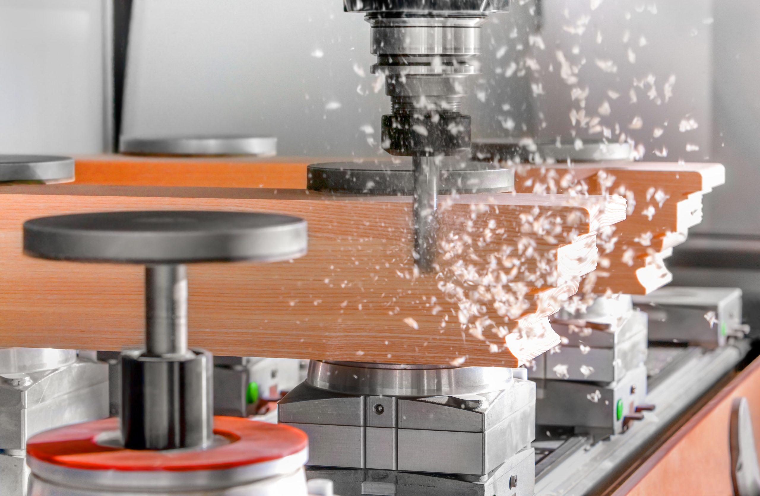
NX CAM Wood
Technische Elemente for the woodworking industry
Recurring design features are THE standard case in the wood working industry. That calls fhe use of Technical Elements. TEs achieve a very high degree of standardization and automation, especially in the woodworking industry. The special module NX CAM Wood enables the connection of wood processing machines in the common formats such as MPR, HOP, FMC, BNV, and many more. Ideal for digital manufacturing in the woodworking industry with Siemens NX.
These satisfied customers trust us already
![]()
You want to learn more about it?
Arrange a quick meeting or a request a demo today
Frequently Asked Questions (FAQs)
Which license model does the TE Toolbox offer?
Both named user and floating licenses are available for the TE Toolbox.
How long does it take to develop a Technical Element?
Technical Elements can usually be implemented within a few hours. However, the exact effort depends primarily on the complexity of the geometry and the required metadata. The creation of the preview images is also included in the development of the technical elements.
Can Technical Elements be revised?
Yes. TEs have a version number so that changes or further refinements of the Technical Elements can be made on an ongoing basis. The user interface of the TE Toolbox reacts responsively to the version number of the TEs, so that the historical dialog is also available for “old” technical elements. If necessary, the current revision levels of the TEs can be upgraded.
What are the steps of an implementation project?
An implementation project is divided into the following phases:
- Requirements
Definition of the requirements in a workshop. Which recurring design features are needed? What metadata is required in the downstream processes such as CAM and CMM? In this step, all departments of the product development process are involved. Ideally, suppliers too, as they too are potentially affected by the transition to a model centric engineering approach. - TE-Development
Structure of the Technical Elements according to the specification from the previous workshops. In this phase it is also decided whether neoapps or the customer will implement the Technical Elements. - Training
Training of users or key users. The duration of the training is usually no more than 4 hours per user. - Deployment
Department-wide or global rollout of the TE Toolbox. Adaptation of the start scripts and installation of the software in the IT environment.
How much time can be saved along the entire process chain?
This question can only be answered for the individual case following an intensive analysis of the actual situation. On request, we will carry out a potential analysis together with you.
Can we use company-specific standards for general tolerances in the TE Toolbox?
Yes. All standards are stored in the form of tables in XML format. Adjustments and extensions are therefore possible with very little effort.